
Preamble
I was wondering whether the expensive Wi-Fi shields (i.e. New Wifi Shield V2.0 RN171 Wireless LAN Module for Arduino or WiFi Shield WiShield V2.0 for Arduino) which go for around $60, could be replaced by a £2 XBee shield and a WI-Fi XBee.
TL;DR – I bought a Yún shield..! 🙂
The Options Available
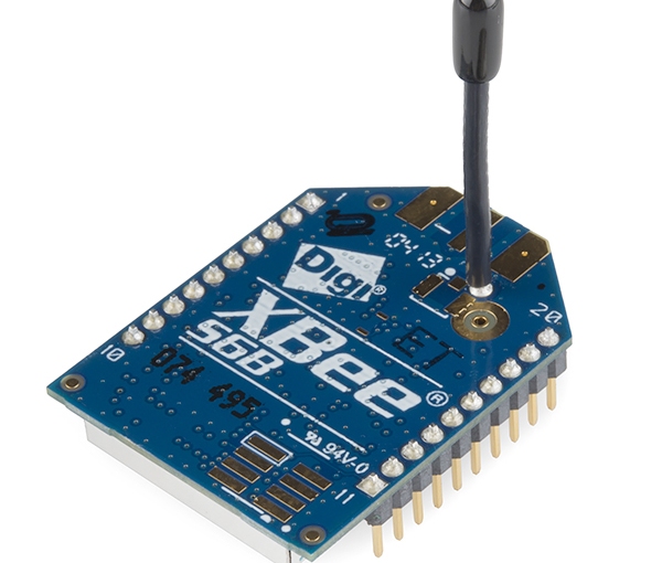
Wi-Fi XBees (S6B) support IEE 802.11. From Digi’s XBee Wi-Fi docs:
OEM Module with Fully Integrated Support for Digi Device Cloud
- Build cloud-connected Wi-Fi prototypes in under an hour
- Popular XBee Through-Hole and Surface-Mount footprints
- Ideal for Industrial Applications that require fast time to market
- Easily connect to a smartphone or tablet for configuration or data transfer
- 802.11b/g/n provides up to 72 Mbps data rate
Unfortunately the Wi-Fi XBees are as expensive, if not more so, than the Wi-Fi shields. For example from:
- SparkFun – XBee WiFi Module – Wire Antenna, goes for $43;
- eBay –MOD, XBEE 2.4GHZ WIFI, WIRE ANT Part # DIGI INTERNATIONAL XB2B-WFWT-001, goes for £42.31 + £12.95;
- eBay – DIGI INTERNATIONAL XB2B-WFST-001 MOD, XBEE 2.4GHZ WIFI, RPSMA CONN goes for £49.22 + £6.95

- There is also the PRO, MOD, XBEE 2.4GHZ WIFI, U.FL CONN Part # DIGI INTERNATIONAL XB24-WFUIT-001, for £67 +£12

- On a more reasonably priced level, there is the Tinysine WiFi-Bee WiFi Wifly Module RN-XV – SMA with Antenna, for £21, but it only supports b/g Wi-Fi. See also WiFi Shield for Arduino. However, it is actually cheaper to buy a better shield (ICSJ010A Wireless SD Shield for Arduino Xbee Module) separately.

Description: The RN-XV module by Roving Networks is a certified Wi-Fi solution especially designed for customer who want to migrate their existing 802.15.4 architecture to a standard TCP/IP based platform without having to redesign their existing hardware. In other words, if your project is set up for XBee and you want to move it to a standard WiFi network, you can drop this in the same socket without any other new hardware.
The RN-XV module is based upon Roving Networks’ robust RN-171 Wi-Fi module and incorporates 802.11 b/g radio, 32 bit processor, TCP/IP stack, real-time clock, crypto accelerator, power management unit and analog sensor interface.The module is pre-loaded with Roving firmware to simplify integration and minimize development time of your application. In the simplest configuration, the hardware only requires four connections (PWR, TX, RX and GND) to create a wireless data connection.
Note1:In order to configure this module, you will need an adapter lets you communicate with the module,before you can plug it and use on other modules.
Features:
- Based on common 802.15.4 XBee footprint
- Ultra low power: 4uA sleep mode, 38mA active
- Onboard TCP/IP stack includes DHCP, UDP, DNS, ARP, ICMP, HTTP client, FTP client and TCP
- Firmware configurable transmit power: 0dBm to 12dBm
- Hardware interfaces:TTL UART
- Host data rate up to 464Kbps over UART
- Supports Adhoc and infrastructure networking
- 8 general purpose digital I/O
- 3 analog sensor inputs
- Real-time clock for time-stamping, auto-sleep, and auto-wakeup modes
- Accepts 3.3VDC regulated power supply
- Wire antenna
Documents:

There is a comparison table for the various Microchip Wifly modules, and an RNXV Evaluation kit, which is similar to a XBee explorer
Here are a couple of useful tutorials to give an Arduino Wi-Fi capability:
/*
 An example sketch to show how to configure a WiFly RN XV with a Teensy 3.1.
 For this example, the Teensy board was mounted on a breadboard, powered over USB.
 Teensy GND and Vin are wired to + and - on the breadboard.
 Teensy pins 7 and 8 (RX3 and TX3) are connected to the WiFly's pins 2 and 3 (TXD and RXD).
 The WiFly has breadboard + running to pin 1 (VDD 3V3) and - to pin 10 (GND).
 This set up was taken from "Setting up the WiFly RN-XV with a Teensy 3.0 "
http://jamesgregson.blogspot.com/2013/03/setting-up-wifly-rn-xv-with-teensy-30.html
A big thanks to James Gregson for his write-up.
One difference here is that this sketch does not use any LCD. All feed back comes
from the Arduino serial monitor.
The bigger difference is that the WiFly configuration is done via Arduino code
instead of being hand-typed into the serial monitor.
Note that this sketch is NOT using the WiFly in AP mode. Do not wire up WiFly pin 8.
Also note that this sketch assumes the WiFly is running version 4.00 of the WiFly
firmware. The behavior of a few things is different than what I found described in
older examples using the WiFly.
The goal of this sketch was to see how to set up a WiFly VX RN (AKA RN171XV) to
connect to a local wireless access point and acquire an IP address using DHCP.
There are assorted WiFly demo sketches on the 'Net but they all seemed not-quite-right
for me. In many cases the demo sketches relied on libraries that wrapped calls to
the WiFly board. Not only did none of these work for me, but the use of a library
obscured the details of what was actually happening, and I wanted to know just what steps
were needed and how things worked.
In the long run a wrapper library would be a Good Thing, since it abstracts a lot of tedious
stuff as well as making things more robust. For example, in this example the configuration
commands are sent and then a fixed delay is used to allow time for the command to take effect.
A far better approach (and one used by every WiFly library I saw) would be to send a command
and then watch the return data for the "OK" prompt. Even better, look for "ERR" and handle
things nicely.
However, the code here is simple, works (for me, at least :) ), and should help illustrate
what you need to do.
A few factoids you may find useful:
 * If you boot the WiFly with pin 8 high (i.e. connected to 3V) then the device goes into soft AP mode.
 * The default IP address is 1.2.3.4 and you can telnet in at port 2000
 * If you find that nothing is behaving as expected you can do a factory reset by toggling power to
 pin 8 five times. (This is sometimes referred to as GPIO9). You need to first power up with GPIO9
 set high, then toggle it five times.
 * Make sure you are using the correct user guide for your WiFly model.
 For this example I used "WiFly Command Reference, Advanced Features & Applications User’s Guide"
 "RN-WIFLYCR-UG Version 1.2r 4/30/13"
 This link might work:
http://www.microchip.com/mymicrochip/filehandler.aspx?ddocname=en557989
 * If and when you get your device appearing on your network (or as an AP) the SSID will clue
 you in about the model.
WiFly-GSX-XX for RN131G/C
WiFly-EXZ-XX for RN171
where XX is the last byte of the module’s MAC address
*/

// <Arduino.h> is needed so that "settings.h" can refer to the String type.
#include <Arduino.h>
#include "settings.h"

/*
 "settings.h" needs to live in the same folder as this sketch and define two strings:
 String ssid = "YourAccessPointSSID";
 String passPhrase = "YourCoolSeekretPassword";
 */

int led = 13; // The LED pin on Teensy 3.1
int commandDelay = 5000; // Hacky, yes.


// Used to buffer Serial stuff
String content = "";
char character;

String content3 = "";
char character3;


// The commands to send to get the WiFly set up.
// The goal was to have a relatively simple
// way to write a list commands that you
// could add to or remove from and not
// have to keep changing some variable tracking
// the number of commands.
// You may have to use a different wlan command depending on
// the security (if any) of your access point.
String cmds[] = {
 "set ip dhcp 1", // 0 means don't get IP form DHCP server. 1 means grab one va DHCP
 "set wlan phrase " + passPhrase,
 "set wlan ssid " + ssid,
 "set wlan auth 4",
 "set wlan join 1",
 "set sys autoconn 1",
 "ext", // Leave command mode
 "" // Required. Indicates the last item when
};

/************************************************************************/
// Read the String array until an empty string.
// Too hacky? Is there a better way to loop over the array of command strings?
// In any event, it works well enough.
void sendCommands(String cmds[]) {
 Serial.println("Send command strings ...");
 int i = 0;
 while( cmds[i].length() > 0 ) {
 Serial.println( cmds[i] );
 Serial3.println( cmds[i] );
 delay(commandDelay);
 while(Serial3.available()) {
 character = Serial3.read();
 content.concat(character);
 }
 if (content != "") { Serial.print(content); }
 i++;
 }
 Serial.println("Command strings are done.");
}

/************************************************************************/
// Useful to show that at least something is happening in case no text output appears.
// E.g. if you wonder if you fried the board or something.
void blink() {
 delay(100);
 digitalWrite(led, HIGH);
 delay(100);
 digitalWrite(led, LOW);
 delay(100);
}


/************************************************************************/
void setup() {
 pinMode(led, OUTPUT); // THIS IS IMPORTANT, or else you never see the light
 Serial3.begin(9600); // UART, RX (D0), TX (D1) are connected to WiFly
 Serial.begin(9600); // Be sure to set USB serial in the IDE.

 blink();

 // A short delay so you have time to start up the serial monitor
 // and see that the sketch is, in fact, running while not missing
 // any useful info
 delay(5000);
 Serial.println("15");
 delay(5000);
 Serial.println("10");
 delay(5000);
 Serial.println("5");
 delay(5000);
 Serial.println("Are we ready?");
 blink();
 Serial.println("Send money ..");
 Serial3.write("$$$"); // Go into command mode.
 delay(250); // The WiFly needs a short delay after the cmd signal
 Serial3.println("");
 sendCommands(cmds);
 delay(3000);
}

/************************************************************************/
void loop() {

 // Copped from http://stackoverflow.com/questions/5697047/convert-serial-read-into-a-useable-string-using-arduino

 String content = "";
 char character;

 String content3 = "";
 char character3;

 while(Serial3.available()) {
 character = Serial3.read();
 content.concat(character);
 }

 if (content != "") {
 Serial.print(content);
 }

 while(Serial.available()) {
 character3 = Serial.read();
 content3.concat(character3);
 }

 if (content3 != "") {
 Serial3.println(content3);
 }

 blink();
}
There is also a library available, see
Yes, you can use that library, I did in my tutorial on the RN-XV:
http://log.liminastudio.com/programming/getting-started-with-the-rn-xv-wifi-module-node-jsHere’s another tutorial that might help:
http://log.liminastudio.com/itp/physical-computing/using-the-rn-xv-wifi-module-as-a-remote-switch
However, I really want to know if it is programmable in the same way as an XBee, i.e. sampling capability and digital I/O. It apparently does, but I’m currently unable to find any examples. There is a manual version B, version A, for the chip NOT the XBee compatible, which suggests that the device is not programmed using the usual AT command, or X-CTU, but with a telnet connection instead, or a Configuration Web Server on the WiFly itself.
The Yún shield
There is also the Newest Iduino Yun Shield Linux WiFi Ethernet USB Compatible for Arduino Board, for £20,

See the blog Arduino Yún Shield for further details.
The Wee serial Wi-Fi module
There is the cheaper Wee Wi-Fi module

See the blog Wee serial Wi-Fi module for further details.
Note
Do not be distracted by apparently cheaper (~£5) BlueTooth XBee modules that are advertised as Wi-Fi, they do not support 802.11, for example the Bee HC-06 Wireless Bluetooth V2.0 Slave Module + V03 Shield Board F Arduino Xbee


3 thoughts on “XBee Wi-Fi”