

Preamble
I could not find a simple guide for wiring up a KK Mini (also known as KK2 Mini). So, this is a quick note on the connections needed to be made, in order to use a KK Mini.
Note: The KK2 Mini is a miniaturised derivative of the KK Multicopter 2 (not the KK Multicopter v5.x – which is, in fact, an earlier version of the KK Multicopter 2 (aka KK2)).
Manual
This is the PDF for the KK 2.1, but it applies to the KK Mini as well: kk2-1-multi-rotor-control-board (original link).
Video
This is a great little video from Hobby King:
HK KK-Mini Multi-Rotor Flight Controller – HobbyKing Daily
Minimal setup
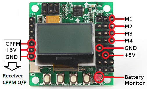
Here is a simple illustration of the bare minimum connections required for a quadcopter:

Don’t do this, as it will not work (as the outputs are connected to GND, but it will not cause any damage):
Do not do (as I did) the following (with respect to the +5V and GND), as this reversed polarity will blow the microcontroller:

Likewise, this is likely to cause damage:

A brief description of the connections:
- M1-M4 go to the ESC control inputs.
- +5V and GND, on the right hand side, come from the ESCs, if they come with BECs, else they will need to be connected to a separate BEC, or regulator. Sometimes a Power Distribution Board (PDB) will come with a BEC built in.
- The order, from left to right, looking at the top of the board, of the ESC connections are: GND, +5V, Signal.
- The battery monitor comes directly from the LiPo battery positive terminal.
- The CPPM/PPM, +5V and GND, on the left hand side, go to the RC receiver output. On a D4R-II, that would simply go to output #1 – with outputs #2 and #3 on the receiver being connected together, to enable CPPM/PPM

Important Note
Do not connect the +5V and GND for the BEC/PDB/Regulator in the reverse sense. Do not assume that the legend on the rear of the board refers to the ESC header pins – the GND and +VB1 markings refer to the solder pads above the markings, and are the reverse of the ESC connections:

The order, from left to right, looking at the top of the board, of the ESC connections are: GND, +5V, Signal.
This is confirmed by looking at a standard servo/ESC cable, which has the wires in the usual GND, 5V, Signal order:

Conversely, the order, from left to right, looking at the rear of the board, of the ESC connections are: Signal, +5V, GND. See below:

Note relating to RC receiver
If the polarity of the power supply is, incorrectly, reversed, at the ESC coonections on the right of the board, then -1.53V is output on the V+ output which goes to the receiver, which could potentially damage an RC receiver if one is connected whilst the reversed power supply is on.
I had a D4R-II connected to my KK Mini when the polarity of the Vcc and GND was reversed. However, I was fortunate that the D4R-II receiver was not damaged.
Other issues
A similar issue is that if you try to power the KK Mini using the ESC (with BEC) cable, but have the cable in reverse (i.e. orange-red-brown en lieu of brown-red-orange), then the KK Mini will not power on, because you have the signal wire connected to ground pin (GND) and ground wire connected to the signal pin. Fortunately, you are unlikely to damage the flight controller as the 5V is not actually reverse polarity as the 5V wire is still connected to the 5V pin. You will only need to orient the ESC cable correctly and the KK Mini should power up.
See kk 2.1 board blank white screen help? : Multicopter – Reddit.
Note on +5V and GND
The ground connections on the inputs and the outputs (i.e. the left and right of the board) are connected.
However, the +5V pins on either side of the board are not connected.

You seem to have the ground and signal pins labeled wrongly in your pictures. Ground should be nearest the edge of the board and signal on the inside pin. I spent some time head-scratching before finally figuring this out.
There’s also a strange thing with this board about the power system being in two separate circuits so both the input and output pin rails may need to be given power if you are using servos- very odd!
The mistake is a shame because your written instructions are good and the picture nice and clear so would be good if you could rectify.
Thanks
John
LikeLike
Many thanks for pointing that out John. Yes, you are obviously correct. I am sorry about that. I have corrected and updated all of the annotated images. Thanks again.
LikeLike