
Preamble
Following on from The case of the broken Pro Micro, I wanted to use my Arduino Ethernet Board, which is basically an Uno and an Ethernet shield fused together on one board, as an AVR programmer for the Pro Micro. For a recounting of this tale see The case of the broken Pro Micro (reprise).
However, before I could use the Arduino Ethernet board as an ISP, I needed to figure out how to program the Arduino Ethernet board, as there is no USB port. The USB-TTL adapter was a CP2102, as shown in the Device Manager snap in of Windows 7

Research
The product page was obviously useless, Arduino – ArduinoBoardEthernet. It says that you can use the AVR pins (with an AVR programmer) or the serial pins (with a USB-FTDI adapter), but does not list which of the six serial pins is which. This is because one is meant to use a FTDI connector, which I do not have (see also Getting started with an Arduino Ethernet board (not shield)).
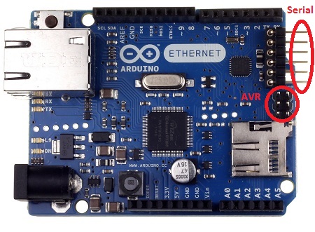
However, from that page, one can download the Eagle files and open the Arduino_Eth08d_MU-REV3.brd file to see which pins are connected to what signal/line, which enabled me to annotate the serial pins:

I was able to verify this with a FTDI cable/connector pinout from the product page for a USB to FTDI connector cable, USB to 3.3v TTL PIN Header Cable

Making the connection
Connecting the USB-FTDI adapter to the serial pins,
DTR => RTS
Rx => Tx
Tx => Rx
and the corresponding 5V and GND pns, obviously. I left CTS, on the Arduino Ethernet board unconnected as there was not a corresponding pin on the USB-FTDI adapter.

Note that it is not necessary to connect the RTS pin on the Arduino. However, if you do not connect the DTR pin of the USB-TTL to the Arduino’s RTS pin, you must hit the reset button at the upload stage of the compile.
If your USB-TTL adapter does not have a DTR line, then you can modify it to send the reset signal, by following this guide, Mod a USB to TTL Serial Adapter (CP2102) to program Arduino Pro Mini like the FTDI Board with Auto-reset.
Uploading the sketch
However, when I used the Arduino IDE to upload Blink, while the sketch appeared to be uploaded to the board (according to the IDE), the LED did not flash.
I later realised that the Arduino Ethernet board does not use Pin 13 for the on-board LED, but rather pin 9 – note that the LED has “L9” next to it. This is because pin 13 is used for SPI timing on the Ethernet board (source: Arduino Ethernet LED 9).
Once I had modified the code, and uploaded it, then the board flashed the on-board LED, as expected.
const int kLED = 9;

// the setup function runs once when you press reset or power the board
void setup() {
// initialize digital pin 9 as an output.
pinMode(kLED, OUTPUT);
}

// the loop function runs over and over again forever
void loop() {
digitalWrite(kLED, HIGH); // turn the LED on (HIGH is the voltage level)
delay(500); // wait for a second
digitalWrite(kLED, LOW); // turn the LED off by making the voltage LOW
delay(500); // wait for a second
}

2 thoughts on “Programming the Arduino Ethernet Board”