
Preamble
Following on from Vaping, why not build your own Mod?
UK Suppliers
Essential reading
Safety with Mechanical/Unregulated mods: A Beginner’s Guide to Your First Mechanical Mod
Useful videos
- An expensive kit, as purchasing the parts seperately is much cheaper, but a useful insight nevertheless, Todd builds a mod – J-Box Renegade Kit from Varitube
Box Mods
Arduino Based
Projects with code and schematics
- Arduino and 110 watts – Open Source – uses OKL2-T20
- You asked mamu it’s coming.
- Code: Rebuild_V_1d.ino – Requires ClickButton (see using ClickButton library for multiplexed buttons)
- Schematic

OpenVape OKL2-T20 - YouTube,VID 20140626 194241
- Mamu’s basic power circuit, without Arduino: Tinkering with the OKL2-T20 20A 110W dc/dc converter…
- DIY arduino mini pro based mod with thermocontrol
- Github: vasimv/ard-smoke – needs:
- U8glib. It is not necessary to visit the Github repo, GitHub: olikraus/u8glib – Arduino Monochrom Graphics Library for LCDs and OLEDs
- MsTimer2 GitHub: PaulStoffregen/MsTimer2 – Run a function using a timer
- Github: vasimv/ard-smoke – needs:
- YouTube, The GhettoVape III – working mod, uses 3034 FET
- Github: code to operate a basic arduino pro-mini based vaporizer with LCD screen.
- Schematic :

Ghetto III schematic - Parts:
- Arduino Pro
- Mini Hammond 1590b project enclosure (IIRC)
- 5v step-up (search ebay)
- Solid insulated copper wire (doorbell wire)
- Solder tools
- 16×2 lcd screen
- 2x Momentary buttons
- 10k resistor Small
- 10k potentiometer (for LCD screen)
- 16 x 2 character LCD screen
- 18650 Battery 18650
- single battery sled
- 3034 N-Fet
- AlexGyver
- YouTube, Vape 220 pt5
- VapeShield. VV/VW/VA Mod Board – If you visit http://ukvapers.org/Thread-VapeShield-VV-VW-VA-Mod-Board?page=80, and read the next 40-50 pages, there’s plenty of info about the build and programming.
- Github: OpenSource Vape/ Smart_PWM_Test – This seems to be the same, or derived from Open Source box mod as the first in the list (Arduino and 110 watts – Open Source, Code: Rebuild_V_1d.ino ), but the repository has moved from google to GitHub, see this post.
- It requires PWM.h from GoogleCode: arduino-pwm-frequency-library (see this answer from Mavidad, to Generating PWM signal 1-2 ms @ 333 Hz). See also PWM.h. Uses NSR020A0X43Z (Naos Raptor 20A), AD8400 (AD8403)
- Schematic 1
- Push Button using DIgiPot AD840/AD8403
- Schematic 2
Also ran – No code
- YouTube, Arduino powered eCig. (eCigDuino)
- TIP31C
- make sure it’s calculated for Vrms. Vmax*duty cycle(0-1) isn’t a true reading.
- You may know, but if you underclock the ATMega it needs less supply voltage. I have some Arduino Pro Mini’s that use ATMEGA328P at 8MHz which run on Vcc=3.3V. Also an ATTiny could shrink things down a lot. ATmel ATTiny85’s are 8-pin DIPS!
- YouTube, 3s Arduino Based Vape – Nifty
- YouTube, Arduino Nano Dampfer Vape Mod PWM I2C Clock LCD – Nifty
- YouTube, Custom Vape Box Mod!
- YouTube, Home rekker, custom made regulated box mod (arduino prototype)
- Buck boost
- make sure you use a proper rated MOSFET.. Usually IRLB3813 and IRLB3034 is suggested… you may have to limit the gate current using a resistor though.
STM32
- DIY Open-source open-hardware TC/Variwatt mod (STM32 based)
- GitHub:vasimv/StmSmoke – Open-source (GPL) STM32F373C8T6 based vaping mod, up to 140W, to use with LiPo 2S 50
Other
- YouTube, Box Mod Build Tutorial
- YouTube, PWM Box Mod Build
DNA
These are self made, LiPo 3S powered devices, although they can take 18650 batteries. They use a series of pre-assembled, and programmed, boards from Evolv and use the eScribe software to customise them. PDF for DNA 200: dna200
From DJLsb Vapes: See Evolv DNA60, DNA250, DNA167 Full Review DNA Mod Giveaway and Escribe Tutorial
DNA75
From DJLsb Vapes: See Evolv DNA 75 C Full Review with eScribe and Theme Editor Tutorial – DJLsb Vapes
DNA40
From DJLsb Vapes: See Evolv DNA 40 Complete Guide and Review
DNA200
This is the first video. From DJLsb Vapes: See Evolv DNA 200 Full Review + TC Charts + Power Charts + EScribe Software Tutorial + Extras – Board review, not mod review 200w 3 cell in series 3 18650, 2 cells gives 133W. Only does 100 W out of the box, required firmware from eScribe. use 200W to ramp up and then use temp control thereafter – don’t vape constantly at 200W. 510 connector is grounded through the case.
Temp control graph, power output graphs. eScribe sets up two sets of properties:
- Battery’s Wh and Charge curves, and;
- Case thermal (TC) properties – ventilation, insulation, material (printed, plastic, ABS, Aluminium)
Points covered in the video, from @16:25:
Review
- Buttons (Up/Down)
- Micro USB charging port
- Buttons wired to the pins on the board
- Quick display explanation (can be ignored)
- @18:43 – Set to defaults (Upload settings)
- Initial question – new coil
- Default display explanation
- Nickel temperature control by default
- Up/Down buttons changes power
- Serial Number and name of the board, by holding power down button down
- Power increments, configurable
- Max power, configurable
- Locked – up and down buttons held down
- Profiles
- Locked – fire button x 5
- Need to lock the resistance, else the board calculates its own resistance. When locked the temperature will not be consist, but makes for a more convenient vape.
- Normal and Stealth – Fire and down buttons held
- @25:43 From the locked screen, hold up and down. This gives you temperature control 200F-600F (10F increments), or turn off. Below 200F switches to °C 100°C-300°C (5°C increments)
- Screen rotation – off by default, can configure on in eScribe and flip the buttons
- Normal and Charging state
- Charging (shows voltage, current and percentage charge)
- Vape while charging
- Maximum charge 1A. Current reduces when battery nears completed charge (VapourShark DNA has 2A)
Software Tutorial
- @29:56 Firmware links, evolvapor.com
- eScribe software – Windows only
- Connecting to the board
- Default name “Evolv DNA200”
- Bricking – you can always manually install the firmware again. When bricked, sometimes eScribe doesn’t recognise the device, but you can reinstall te firmware (not sure how).
- Help
- @38:45 – General Tab
- Download/Upload settings
- Custom Profiles
- Custom screens:128×32 pixels, B/W
- Profile Settings: Temperature/Material/Power/Pre-heat
- Load/Save/Copy profile
- Atomiser Analyser
- Temp reading until you set the thermal calibration
- Custom materials –
- @47:26 – Themes Tab
- Custom screen
- New Coil
- Lock clicks (x5)
- Kanthal
- Temperature protected
- Return to researcher
- Battery Meter
- Select which screen display the battery
- Look and feel
- Watt Increments (for both Press and Hold)
- @54:15 – Screen Tab
- Flip screen
- Errors
- Battery Cells displayed
- Brightness
- Fades too…
- idle/charger
- Time
- Active
- Idle
- Fade In
- Fade Out
- @57:20 – Mod Tab
- Charge mode
- Maximise puffs
- Charges
- Power Limit (100 -> 200 W). For 2 x 18650 use 130 W
- Manufacturers Settings
- Battery
- Number of Cells
- Capacity (Watt-Hour)
- Watt-Hour calculator
- Cell soft cutoff
- Discharge Profile
- Battery Analyser (recommended!!!)
- Takes a long time
- Electrical profile
- Mod resistance
- Mechanical Profile
- Up/Down flip
- Thermal Profile
- Shape
- Material
- Ventilation
- Charge mode
- @1:03:12 – Research Tab
- Data Acquisition
- Usage, etc.
- Experimental Setup
- Data Acquisition
- @1:03:33 – Uploading a fully pre-configuration
- @1:04:55 – Device Monitor
- Battery
- Charge
- USB Power,
- Voltage,
- current
- Pack
- cells
- Puff
- Power
- Current
- Voltage
- Temperature
- Statistics
- ECig Stats – statistics application
- Controls
- Record
- Pause/Save graph
- Trigger puff
- Set power
- Set temp
- Diagnostics – USB recovery charging, for dead battery
- Reset statistics
- Battery
Analysis
- Temperature Graphs
- Power graphs – The DNA200 is an accurate board. Each mod is a different device, with different thermal properties.
- Batteries Sony VTC5 or LG HB6
Conclusions
- Mods review
- @1:17:36, 3D Printed case by Zak, Shapeways, see his Vaping Moderation channel: Escribe Walkthrough (NEW), and many other videos
- Not for beginners
- 200W good for a fast ramp up
- Moans
- Should not have a constant watt display – should only use temperature control
- Steam engine is more accurate, but the TCR gives a better vape
- Upload Settings should be Download Settings
- No screen issues
- Wismec DNA died – whilst using battery analyser, board just died
- +/- buttons should not be inscribed
- 2A charging should be enabled – requires separate charge board. I prefer 0.5C (<1C charging) it is better to be patient than have LiPo fires
- OSX version to be released, as is Linux
DNA250
There are a number of DNA250 mods. From DJLsb Vapes: See Vaporized Nomads Boss3000 DNA250 Full Review – DJLsb Vapes. See also Reply to DJLSB’s BOSS 3000 Review
Comes with a varitube 510 connector, big throw. Charge 3S 1800 mAh – 1.5C Charge rate.
Power 1-250W. Evolv’s DNA 200 boards can die for no reason. eScribe won’t connect.Temp coeffs off for Ni200 (should be 0.00620), SS 316/316Land Ti are slightly off. No temperature control in NiCr.
Pros:
- Well made
- Rounded edges
- Magnets are strong
- Engraving
- Varitube 510
- MiTech switch
Cons:
- Customer service – communication
- One year warranty
- PRICE, overpriced at $400-500
- Can’t change LiPo, no plug, directly soldered
- Plus and Minus buttons rattle – should use sticky foam
- MiTech switch rattle
- Inaccurate temp
- Ni60-80 do nothing
- Will no connect to eScribe
To buy the chip set:
- Authentic Evolv DNA250 Board – Brand New Retail Box, £46.94 $60.95
- Dripp3d Evolv DNA 250 £46.21, $60
- DNA 250 CHIP SET – EVOLV, £59.95
- $80.00-DNA 250 w/Detachable Screen
The DNA 250 is the NEW power regulated board from Evolv. It features Evolv’s patented Wattage Control, Temperature Protection, Preheat, Digital User Controls, OLED Screen, Onboard Buttons and Synchronous Rectification for maximum battery life and minimal heat generation. The DNA 200 runs from a 3 cell lithium polymer battery, and features cell-by-cell battery monitoring and integrated balance charger. The USB port and Evolv’s EScribe software can be used to customize or monitor the user experience. It is the most advanced personal vaporizer controller ever made. The DNA 200 is vaping down to a science.
- 250w of power
- USB 2a balance charger inbuilt
- Firmware upgradable
- Input voltage 9-12.6vdc so 3 high quality 18650’s in series or a 3s Lipo. Dual 18650 is also possible
- Comes configured for Ni200 but any wire can have it’s TCR entered
- JST-XH 3S balance plug included but needs to be attached by end user
- On board replacable fuse, manufacturer Schurter , part number 3413.0332.22
Dripp3D DNA kits
Check out Dripp3D‘s kits:
- DNA 250, £95 + £17.28 (LiPo 18650 orNanoTech 3S 25-50C 1300 mAh) – On Dripp3D’s website
- DNA 200, £90 + £17.28 (LiPo 18650 or NanoTech 3S 25-50C 1300 mAh)
- DNA 75, £60 + £17.28
- 1550P PWM or Unregulated £45/35 + £17.28 (2 x 18650) (Series or Series/Parallel)
- 1590A PWM or Unregulated £42/35 + £17.28 (2 x 18650) (Series or Series/Parallel)
- 1590B PWM or Unregulated £50/42 + £17.28 (Both 3 x 18650 or 2×26650) (Series or Series/Parallel)
- 1590G PWM or Unregulated £45/35 + £17.28 (2 x 18650) (Series or Series/Parallel)
Basic Box Mods
These box mods do not use a microcontroller.
The most basic – using a MOSFET (3034 or 3813)
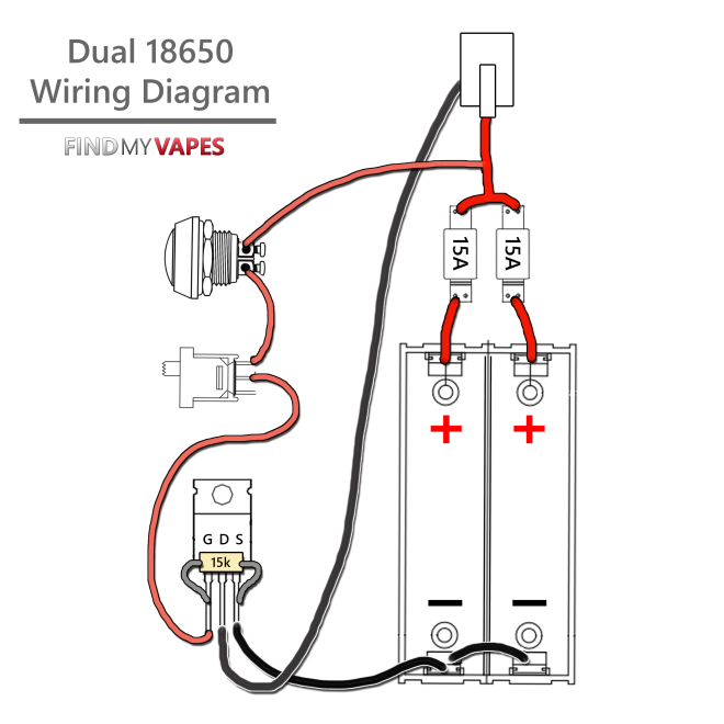
YouTube, from Find My Vapes, see How to Build Unregulated Dual 18650 Box Mod, read also How to Build Unregulated Dual 18650 Box Mod with MOSFET – A very simple mod box, with no microcontroller. It is a good base to start with, to build an Arduino controlled box mod on to. Uses:
- Hammond 1590G case
- IRLB3034PBF MOSFET N CH MOSFET, 40V, 195A, TO-220AB
- 15kΩ resistor
- 2x15A resettable fuses – wired in parallel to give 30A
- battery sled – wired in parallel
- 510 connector
- Standard firing switch
- Master on/off switch
- SWG16 – flex, multi strand – high current: battery, 510, and MOSFET
- SWG20 – flex
- 2 x 18650 batteries
- 4 x magnets
Use a step drill bit to drill the holes.
The next step – using OKR T10
YouTube, from Find My Vapes, see How to Build OKR Box Mod Tutorial, see also How to Build an OKR Box Mod Tutorial, OKR allows voltage adjustment between 3.4 and 6 volts, it is used instead of MOSSFET. Uses:
- OKR T10
- Hammond 1590G case
- battery sled – wired in series – keystone dual
- 510 connector
- Firing switch
- 200 Ohm potentiometer
- Master on/off switch
- 1 kohm resistor (pins 1 and 3 OKR)
- 220 ohm series with pot
- zener 5.6V diode
- SWG 20 wire
- magnets 1/4″x1/8″
- Epoxy

Note: 0.5 Ohms minimum coil resistance.
Note: No reverse battery protection but does have low voltage protection
On eBay:
- Murata OKR-T/10-W12-C Voltage Power Converter Chip DC/DC OKR-T 10-Amp Free Ship, US $13.50, Approximately £10.39 + US $13.50 (approx. £10.39)
More power – using OKL-T20
YouTube, from Find My Vapes, see How to Build OKL T20 Box Mod Tutorial, see also How to Build OKL T20 Box Mod Tutorial OKL T20, 110W 20A. In fact, the device is a OKL2-T20, from Murata, and handles 100W.
- Input voltage is 4.5 to 14 volts.
- Output voltage is (for our purposes) 3.5 to 5.5 volts.
- Maximum output current is 20 AMPS.
- Maximum output power is 100 watts.
The PDF is here, okl2-t20-w12, link. This mod has reverse battery protection, but appears to be lacking low voltage protection. Uses:
- OKL T20 3.5-5.5V regulation
- Battery sled – in series
- 510 Varitube
- Fire switch
- 1kohm potentiometer
- master on/off
- P-FET – for reverse polarity protection, SUP75P03-07-E3, eBay: VISHAY, SUP75P03-07-E3, MOSFET, P CH, 30V, 75A, TO220AB, £3.82
- 20k resistor
- 1k43 resistor
- magnet
- SWG18
- SWG24

More refined – using OKL2-T20
Basic circuit: Tinkering with the OKL2-T20 20A 110W dc/dc converter…

These are not cheap:
- MURATA P SOLUTIONS OKL2-T/20-W12N2-C DC-DC CONVERTER NON ISO POL 1O/P 100W 20A, US $23.02 Approximately £17.72 + Free
This is a very good review, OKL T20 Chip Review:
- Input voltage is 4.5 to 14 volts.
- Output voltage is (for our purposes) 3.5 to 5.5 volts.
- Maximum output current is 20 AMPS.
- Maximum output power is 100 watts.
Less refined – OKL2-T20
From Murata OKL2-T20 Wiring Diagram, no battery protection, but has an optional battery meter:

Another unregulated mod
From Low voltage protection in unregulated MOSFET box?, MOSFET mod

With a USB charger

A raptor circuit from Mamu
From Tinkering with the Naos Raptor – 20A, 120W dc/dc converter…

Notes on firing MOSFETs
From GENUINE IRLB3813 MOSFET • 15kΩ DALE RESISTOR • BETTER THAN USUAL FET FOR BOX MOD:
Why are IRLB3813 MOSFETS better than IRLB3034 MOSFETS?
1. They’re less likely to burn out
2. They switch on way fasterFirst, let’s take a look at the gate to source voltage (Vgs). Having a lower Vgs gives you a wider margin between operate and damage levels. I’ve personally drained batteries down to 2.4V accidentally, at which point they would not even fire a coil. This is VERY VERY BAD. This is how you break a MOSFET and vent your batteries at the same time. CORRECTION – This is how you break an IRLB3034 which has a Vgs of 2.5V. Voltage at the gate of an IRLB3813 is 1.9V making it very difficult to damage with IMR batteries.
Second, look at those timing statistics! Trust me, the difference is noticeable even from across the room. Your friend is still tugging on his boat while you done went zero to one hundred real quick.
Ignore the Vds and the continuous drain current. Sure, the IRLB3034 shows 40V and 343A, and that looks all big and bad compared to the IRLB3813, but think about it… we will never want nor need anything delivering 30V 260A anywhere near our faces, let alone in our mouths. I guess the only perceivable con is that the IRLB3813 has a slightly higher drain to source resistance (Rds On). Not that the .45 mOhms difference would cause any noticeable voltage drop whatsoever, but with two of them in parallel, that literally cuts the resistance in half, just like adding a second coil to your atomizer.
Why should I buy your IRLB3813 MOSFETS when I can get two for a dollar from other vendors?1. Ours are made in the USA.
2. It’s actually cheaper because you’ll have to keep replacing the clones which are guaranteed to break.In my amateur DIY modding days, I bought several batches of cheap, clone MOSFETS and every single one of them failed within the first few months of use. I’m sure you can imagine the amount of time and stress of having to repair so many mods. When it comes to the real thing, there is NO COMPARISON. I’m going on two years using a single IRLB3813 in my box.
Not only do we guarantee genuine Infineon/International Rectifier IRLB3813 MOSFETS manufactured in the USA (not drop shipped from China like many, many vendors – not saying any names), we’re also throwing in a genuine Vishay Dale 1/4W 15kOhm metal-film resistor with 1% tolerance also made in the USA. These are not cheap components, especially compared to what’s readily available to you elsewhere. We’re not interested in minimizing expenses or delivering cheap knock-offs. We simply want you to have the MOST RELIABLE and HIGHEST QUALITY that you can find. We just don’t want you to make the same mistakes nor experience the same level of frustration that we’ve dealt with, along with many other DIYers and even trusted manufacturers (again, not saying any names).

Components
Case
Hammond 1590A/B, Sizes:
- 1590A: 9.2*3.7*3.3 cm
- 1590B: 11.1*6.0*3.1 cm
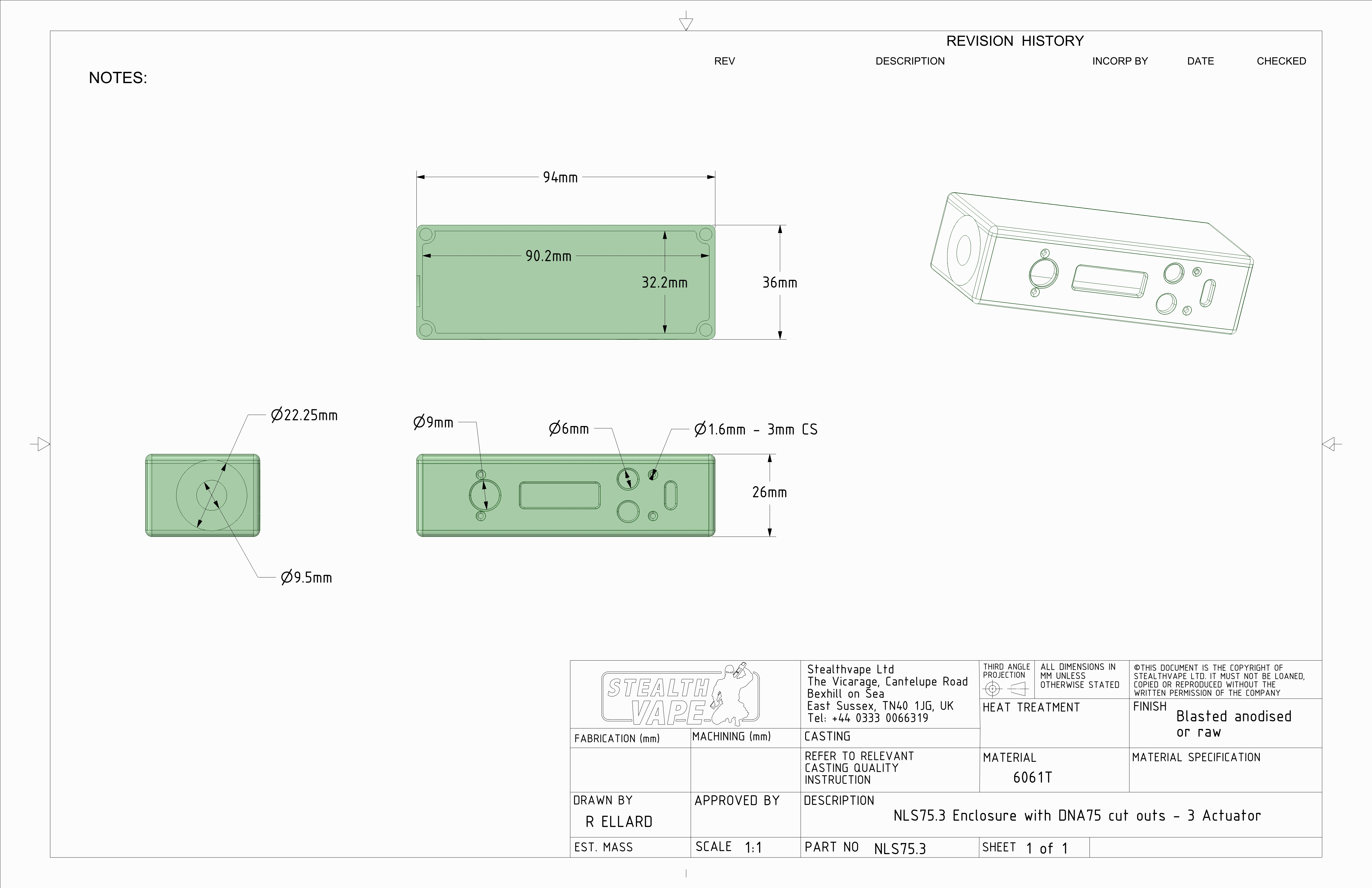
The Screen size of the DNA is 0.91” diagonal white OLED screen, 128×32 pixels. Dimensions (from Monochrome 128×32 I2C OLED graphic display):
- Display area (mm) : 25 x 7
- Panel Size (mm):30.00 × 11.50 × 1.45
- Active Area (mm):22.384 × 5.584
So the cut out for the screen, on the pre-cut cases, for DNA boards, is not compatible with the 1.44″ SPI display, nor the 0.96″ colour OLED (21.744(W)x10.864(H)mm) (from Datasheet 128×64 OLED Module SPI 0.96″Graphic Displays,White on Black). An additional cut out would be required in the side of the case, rather than the edge. The cut out is for the 0.91″ display:
- 0.91″128×32 IIC I2C White DIY OLED LCD Display Module 3.3V Fr PIC Arduino Hot im, US $1.99 Approximately £1.52 + US $0.99 (approx. £0.75) – Uses Adafruit_SSD1306 Arduino library. See 0.91″ SSD1306
Case cut outs, from Stealth

On eBay,
- Alpinetech P+ CNC Box with 200 250 75 Cutouts TYPE1 Buttons&Magnets Included, $16 + $13, pre-drilled (including 510 connector hole) and comes with buttons, in many colours
- Hammond Box 1590G 1590GBK Aluminum Box Ideal for Electronic Free Shipping in USA, £6.89 + £10.39
- Cheapest, Aluminum Stomp Box Effects Pedal Enclosure FOR Guitar Hotsell NEW I5, AU $5.52, Approximately £3.37
For the case, lid and magnets:
- From IPV2 50 watt Box mod… mod using magnets! (magnet door mod) place magnets of opposing polarities for case lid, so that it can only be replaced one way round.
3D Printed 18650 cell sled
- 3D Printed Sled for Hammond 1590B Dual 18650 Surface Bridge, US $7.50, Approximately £5.72 + US $19.10 (approx. £14.56)


- 3D Printed Dual 18650 Slim Sled, US $4.00, Approximately £3.05, + US $19.04 (approx. £14.51)


Gaskets
Display
The cut out in the DNA case is for the 0.91″ display:
- 0.91″128×32 IIC I2C White DIY OLED LCD Display Module 3.3V Fr PIC Arduino Hot im, US $1.99 Approximately £1.52 + US $0.99 (approx. £0.75) – Uses Adafruit_SSD1306 Arduino library. See 0.91″ SSD1306
Switches
Fire button
Momentary contact
16 mm
- 16mm Anti-Vandal Momentary Stainless Steel Metal Push Button Switch Raised Top, $0.99, £0.76 – shallow thread, would protrude too much into case


12 mm
- 1Pcs Mini 12mm Waterproof Momentary ON/OFF Push Button Round Switch Random Color, C$ 0.99, £0.61 – shallow thread, would protrude too much into case
- 12V 9.5mm LED Metal Power Momentary Push Button Switch IP65 for Car DIY Modified, 2.5 cm depth, 12 mm hole
9 mm
- 1Pcs 8mm Mini 1NO 2Pin Metal Momentary Push Button Switch 0.5A/250VAC NEW, $1.88

9 mm switch dimensions
Master on/off switches
19/20mm
- Waterproof On/Off Round Rocker Switch + Cover Car Dashboard Dash Boat 12V, C$ 0.99, £0.61 – – it is quite deep
- ON/OFF Car 12V Round Rocker Dot Boat LED Light Toggle Switch+ Waterproof Cover – has LED, but it fires at 12V, so pointless, unless you use a 4S LiPo.
Square
Slide
- 20pcs SS12D00G4 SPDT 1P2T 2 Position 3 Pin PCB Panel Vertical Slide Switch CAON, C$0.99 £0.61 – for both disarming fire button, and a second for turning off the device
Fuses
The 15A fuses seem pricey (well, the shipping does),
- Littelfuse, Resettable Fuses – PPTC 77 ACT TEMP 15A HOLD (3 pieces) TE, Raychem, $6.99 + $16.40
- Resettable Fuses – PPTC 77 ACT TEMP 15A HOLD 5 pieces, US $17.68, Approximately £13.61
and I wonder if it is possible to switch for PolyFuses, such as:
- 5Pcs New JinKe Polymer PPTC PTC DIP Resettable Fuse 16V 15A JK16-1500, for $3.79 + Free. – But the trip time is too slow
See How does a fuse blow at its current rating, regardless of voltage? and SAFETY FUSES FOR MECHS. and 15a Resettable Fuses
From RS, Bourns Surface Mount Resettable Fuse, 28V dc, £3.04 (£0.608 each)
Using fuses in parallel is an inherently bad idea, see Polyfuses in parallel for shorter trip time?, it is much better to use one correctly rated fuse. Also, polyfuses will not give the same safety once they have triggered. Better to use a traditional replaceable fuse.
5x20mm quick blow fuses
- 20Pcs 250V Quick Blow Glass Tube Fuses 5 x 20mm 0.1A 0.2A 0.25A 0.5A~30A, £0.99 for 15A
- 12PCS BLX-A type PCB Mount FUSE HOLDER 5MM X 20MM 15A/125v SOLDER HOLDERS, £0.99
- Pair Auto Car Truck Motorcycle Wire Cable Inline Glass Fuse Box 15A, £1.12, uses 5x20mm fuses
- 10Pcs/set 5x20mm Quick Blow Glass Tube Fast Acting Fuse 1-20A FF, $0.99
- 50Pcs 10 Values 0.2A-15A 250V Assorted Fuses Glass Tube Fast Rapid Blow 5x20mm, $1.77
Automotive Fuses:
- 30Pcs 32V 30A 30 AMP Mini Automotive Car Truck SUV Blade Fuses Green K5R2, £0.99
- In-Line Standard Blade Fuse Holder + 6 Fuse 12V 5/10/15/20/25/30A Car Automotive, £0.99
- 2017 Car Blade Fuse Holder 12V Mini Blade Holder For 5A 10A 15A 20A 30A Fuses, £0.76
Further reading around the subject, as I still am not sure about which fuse type, and which holding and blow currents to use:
- About fuses and choosing the appropriate fuse for your mod, and;
- Guys who built an unregulated box mod…
P-FET
For reverse polarity protection, PFET SUP75P03-07-E3:
- eBay, VISHAY, SUP75P03-07-E3, MOSFET, P CH, 30V, 75A, TO220AB, £3.82 – seems pricey
- Farnell, SUP75P03-07-E3 – MOSFET Transistor, P Channel, -75 A, -30 V, 5.5 mohm, -10 V, -1 V, £1.53 + Shipping (pricey at £3.95)
- RS, Vishay SUP75P03-07-E3 P-channel MOSFET, 75 A, 30 V, 3-Pin TO-220AB, £1.73 + VAT (£0.35) = £2.08
OKR-T10
For regulated
- Murata OKR-T/10-W12-C Voltage Power Converter Chip DC/DC OKR-T 10-Amp Free Ship, US $13.50, Approximately £10.39 + US $13.50 (approx. £10.39)
OKL2-T20
For regulated and more power
- MURATA P SOLUTIONS OKL2-T/20-W12N2-C DC-DC CONVERTER NON ISO POL 1O/P 100W 20A, US $23.02 Approximately £17.72 + Free
MOSFET
For Unregulated
- 2PCS IRLB3034PBF IRLB3034 HEXFET Power MOSFET TO-220, US $0.99, Approximately £0.76
30K Resistor
This is for the MOSFET, Gate to GND. I don’t believe that this particular Vishay Dale resistor is actually required – any 15k resistor will do, as it is not current bearing
- Vishay Dale 0.25W 15k
LiPo Sled
There are two types of contact:
- spring; and;

18650 2xCell Sled with springs - metal springy tabs

18650 2xCell Sledge with tabs
The tabs are preferable as there can be a resistance (3Ω) associated with the spring, see The GhettoVape III, and also the spring can eventually break. Note that the tabs will need the bottom of the springy tab bent/curved inwards, towards the back of the enclosure, in order to prevent the bottom of the springy tab from tearing the 18650 cell’s plastic wrap (see How to Build Unregulated Dual 18650 Box Mod at @5:40:

On eBay:
4 cells
- Fine DIY Black Storage Holder Case For 4 x 18650 3.7V Rechargeable Batteries Hot,
US $1.39, Approximately £1.06
- In parallel, 1pc 4×18650 in Parallel 3.7V Pole Battery Box Holder Batteries Case Box,
US $1.25, Approximately £0.96
You can get them cheaper in auctions, I paid £0.56.
2 cells
- 2-Slot Storage Box Holder Case For 2x Li-ion Lithium 18650 3.7V Battery With Pin, £0.99
- Plastic Battery Storage Case Box Holder For 2 x 18650 3.7V With Wire Leads MR, £0.99
- Cheapest, Plastic 2-Slot Storage Holder Case For 2x Li-ion Lithium 18650 Battery With Pin, £0.73
1 cell
- Plastic 1-Slot Box Holder Case For 1x Li-ion 18650 3.7V Battery With Pin, C$0.99, £0.60
- 4Pcs Cell 18650 Battery Rechargeable 3.7V Clip Holder Case Box With Wire Lead B5, C$4.16
- A slightly different type, not as sturdy looking, and more expensive, 1Pcs Battery Case Storage Holder Nylon Shell Brass SMD SMT 1×18650 3.7V B5, C$1.88
Note: Pay attention, some of the sleds come pre-wired with leads in a series or parallel configuration. It is best to get one without wires configured, so that you can choose to make a parallel or series sled, as you require.
Buck Booster Step up
- To 3.3V – 2 in 1 DC DC Step-Down & Step-Up Converter 1.8V-5V 3V 3.7V to 3.3V Power Module, £0.99
- To 5V – 2A DC-DC Boost Step Up 2V~24V To 3.3V 5V 6V 9V 12V Adjustable Voltage Converter, $0.99
USB connector
For charging, you will need a vertical mounted USB connector., for the connector to poke out of the side of the case, (assuming that you use a PCB flush against the side. These vertically mounted USB connectors (micro and mini) are not that common and are more expensive than the standard horizontally mounted connectors:
- Mini USB Type B Female 5 Pin DIP 2 pin Vertical Leg PCB Socket Connector – UK, £10.20 + 0.99

Vertical Mini USB - 2x Micro USB Socket 5P Female Plug Repair Replacement Part Vertical Solder Pin J, AU $8.95, Approximately £5.42, normally AU $9.95

Vertical Micro USB
The mounting of the micro USB connector in the Smok Alien mod, is a very good example of the strong and durable, through PCB, mounting technique, using a secondary piece of daughter PCB as extra strength, see SMOK Alien Kit Full Review + Firmware Upgrade Tutorial + Charts and Graphs – DJLsb Vapes at 41:38.


From RS
- Wurth Elektronik Vertical Through Hole Type B Version 2.0 Micro USB Connector Socket, 30 V ac, 1.8A WR-COM, £1.88
- Wurth Elektronik Vertical Through Hole Type AB Version 2.0 Micro USB Connector Socket, 30 V ac, 1.8A WR-COM, £1.88
- Molex Vertical SMT Type B Micro USB Connector Socket, 30 V ac, 1.8A 105133, £0.602 (but must buy 5 and they are surface mount)
Common battery mistakes
From VAPING BATTERY SAFETY 101: 6 COMMON MISTAKES VAPERS MAKE WITH BATTERIES:
- No loose batteries – always use a case
- Reverse polarity protection – put the batteries in the correct orientation
- Use the right charger – you don’t want a high current charger (stick to 1A or below), and you need over charge protection
- Over discharge – don’t use the batteries to low, 3.8 V limit
- Too low resistance coils – stick to 0.2 A (gives a 21 A draw) or above (0.05ohms uses 84 A)
- Coils touching top cap – creates a short circuit
From LiPo: How low can you go? (voltage per cell)
a battery voltage of 3.7V/cell (unloaded) tells you that you have used 80% of the batteries capacity
Bottles
From UK
- 5 x 10ml Amber Glass Dropper Bottle With Glass Pipette, £7.49
- FIVE 20ml Amber Brown Glass Bottles with Dropper Pipettes, £7.57
- 5 x 30ml Brown Amber Glass Bottles with Glass Pipette Dropper – Aromatherapy, £7.89
- 5 x 50ml Brown Amber Glass Bottles with Glass Pipette Dropper – Aromatherapy, £9.89
- FIVE 100ml Amber Glass Bottles with Dropper Pipettes, £14.52
510 heatsinks
- Heat Sink 510 Adapter Kühler Verdampfer Aluminium Heatsink Driptip, EUR 1.35/1.59, Approximately £1.21/1.42 for 1st/2nd generation
- Stainless Steel 22mm Finned Heat Sink Adapter For 510 Thread RDA RBA Tank 2nd, US $1.49, Approximately £1.14 – second generation
- Newest Stainless Steel 22mm Finned Heat Sink Adapter For 510 Thread RDA RBA Tank, US $1.39, Approximately £1.06
- 22mm Stainless Steel Finned Heat Sink Adapter For 510 Thread RDA RBA Tank 2017, US $1.35, Approximately £1.03
Balanced charger board
- YiHi 9V Balancing Charger Board, £6.99 – pricey but works from 9V 3.5 mm plug adapter

One thought on “Vaping – Box Mods”