

Preamble
Following on from the single board Arduino Boy, see Chiptunes, I thought that it would be prudent to make some notes about barebones Arduino schematics, that can then be incorporated into single board designs
See also
Links
- ATMEGA8 BREADBOARD CIRCUIT – PART 1 OF 3 – POWER SUPPLY
- ATMEGA8 BREADBOARD CIRCUIT – PART 2 OF 3 – THE MICROCONTROLLER
- ATMEGA8 BREADBOARD CIRCUIT – PART 3 OF 3 – THE FIRMWARE
- Arduino – Building an Arduino on a Breadboard
- Nick Gammon – How to make an Arduino-compatible minimal board
- Parts list – Barebones Arduino Wish List
- SparkFun – Using EAGLE: Schematic
- Instructables – Build your own Arduino Bare Bone System
- Instructables – YABBAS – One of the smallest stripboard layouts.
- Schematics
Arduino Uno by sections
Only three sections are actually required for a functioning Arduino (and even these can be reduced to bare minimums (although the complete set of components is required for stability):
- Regulated supply – bare minimum: 100 nF ceramic next to the VCC and GND pins
- Reset circuitry – bare minimum: 10 kΩ pullup resistor
- Oscillator – bare minimum ceramic oscillator, or use internal timer
The other parts can be added if you need them.
Regulated Supply
Use a 7805SR which is a switching regulator, preferable to the LM7803 linear regulator.
Either side of the 7805 regulator (input and output respectively), use the following 35V and 10 V rated electrolytic capacitors, for the input/output respectively:
- From a battery – 0.33 µF and 0.1 µF (ATMEGA8 BREADBOARD CIRCUIT – PART 1 OF 3 – POWER SUPPLY). To me these values seem a little on the low side.
- From a transformer, and rectified supply – 10 µF and 10 µF (Building an Arduino on a Breadboard)
- 10 µF and 1 µF (from https://www.arduino.cc/en/Main/StandaloneAssembly)
- 100 µF (25V) and 100 µF (10V) and a 100 nF ceramic right next to the VCC and GND pins (YABBAS)

Useful for sanity checking to see if there is actually power applied:
- LED and 330/220 Ω resistor
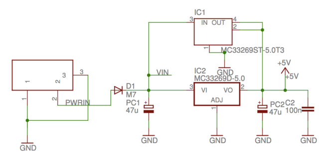
Looking at the regulator circuit used on an actual Arduino Uno, from the Schematic, it can be seen that 47 µF capacitors are used, as well as a 100 nF capacitor for the higher frequency filtering:
Oscillator
Use
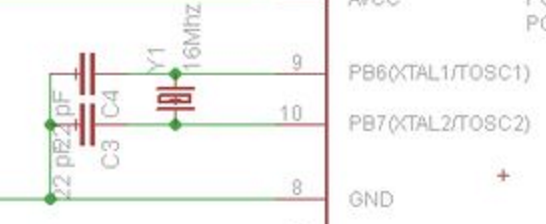
- 16 MHz Crystal
- 2 x 22 pF (How to make an Arduino-compatible minimal board)
or, if timing accuracy is not important
Reset circuit
Use
- 10 kΩ pull up
- Optional – OMRON push button
- Optional – capacitor to DTR:
- 1 µF from Build your own Arduino Bare Bone System
- 100 nF ceramic from YABBAS – this seems to make more sense

Programmer
OPTIONAL: Only required if you are going to program the ATmega8 in-situ.
From Using EAGLE: Schematic, 2×3 AVR Programming Header

Analogue Voltage reference
OPTIONAL: If using Analogue input (ADC). from Analogue to digital conversion on an ATmega168, use an inductor and capacitor to stabilise the analogue reference voltage
Use
- 100 nF
- 10 µH
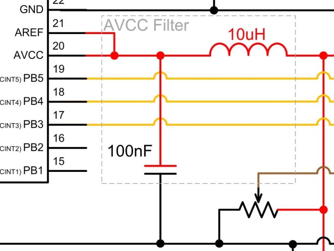
At the very least, Aref should be connected to GND via a 100 nF capacitor, even if not connected directly to 5 V or some other reference voltage (source? Arduino PCB issue and Please help with my custom ATMega328 PCB [on hold])
Additionally, in the rare case of switching between external and internal reference voltages, a 5 k resistor should be employed, from analogueReference():
Warning
Don’t use anything less than 0V or more than 5V for external reference voltage on the AREF pin! If you’re using an external reference on the AREF pin, you must set the analog reference to EXTERNAL before calling analogRead(). Otherwise, you will short together the active reference voltage (internally generated) and the AREF pin, possibly damaging the microcontroller on your Arduino board.
Alternatively, you can connect the external reference voltage to the AREF pin through a 5K resistor, allowing you to switch between external and internal reference voltages. Note that the resistor will alter the voltage that gets used as the reference because there is an internal 32K resistor on the AREF pin. The two act as a voltage divider, so, for example, 2.5V applied through the resistor will yield 2.5 * 32 / (32 + 5) = ~2.2V at the AREF pin.
Test LED
OPTIONAL: If you want a visual output, for test or other purposes
Use
- LED and 330/220 Ω resistor
Rx/Tx LED
OPTIONAL: If using the Rx/Tx pins for serial I/O
Use
- 2 x LED and 330/220 Ω resistor

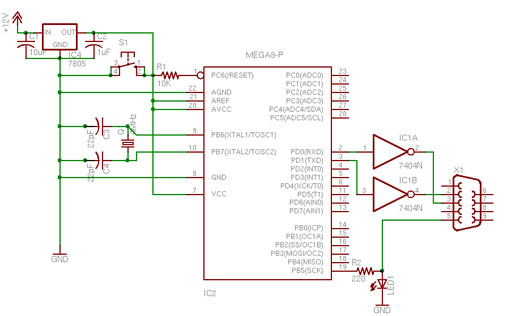
RS232 connector
OPTIONAL: If using the Rx/Tx pins for serial I/O
Use
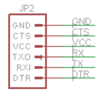
- 6-Pin Serial Programming Header, (ARDUINO_SERIAL_PROGRAMPTH), for:
- GND
- CTS
- VCC
- RX
- TX
- DTR
Note that you may need to employ a 10 k pulldown resistor for the Rx pin. This is for ATmega8 ICs that have a bootloader, and which have slow start up times, due to the bootloader reading noise on the floating Rx pin. See Note 6:
Why doesn’t my sketch start when I’m powering the board with an external power supply? (Arduino Diecimila or earlier)
Because the RX pin is unconnected, the bootloader on the board may be seeing garbage data coming in, meaning that it never times out and starts your sketch. Try tying the RX pin to ground with a 10K resistor (or connecting RX directly to the TX pin).
Power jack
OPTIONAL
Use
- 5.5mm Barrel Jack (PTH)
- 0.1µF Ceramic Capacitor between +V input and GND

Analogue Connector
OPTIONAL
Use
- 8-Pin 0.1″ Header (M081X08)
3V3 Supply
OPTIONAL: If you require a 3V3 supply
Use:
- 7803SR (switching regulator, preferable to LM7803, LM1117T-3.3 or LM317 which are linear regulators => high heat dissipation)
- 2 x 10 µF (35 V and 10 V) electrolytic capacitors
Schematics


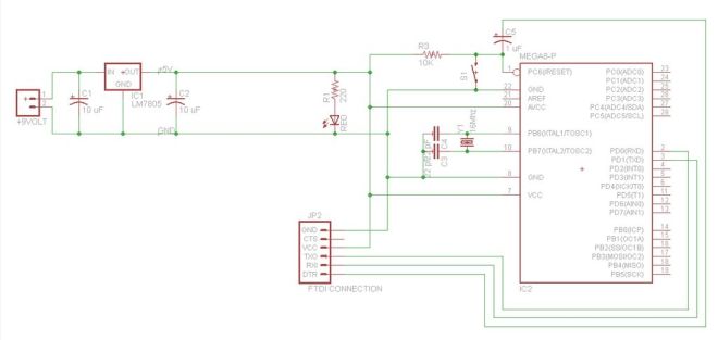
From Instructables – Build your own Arduino Bare Bone System
